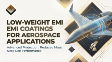
Introduction
Modern aerospace engineers face an unrelenting design paradox: aircraft and spacecraft demand increasingly sophisticated, densely packed electronics to support advanced avionics, communication systems, and autonomous capabilities, yet every gram of electromagnetic interference (EMI) shielding competes directly with fuel, payload, and operational range. According to the Society of Aeronautical Weight Engineers, electrical wiring systems account for 10–40% of total electrical system weight, with wiring alone consuming 1–2% of an aircraft's empty weight. Traditional copper-based EMI shields and metal braids compound that burden—copper's density of 8.96 g/cc means even thin cable jackets add measurable mass across kilometers of harnesses.
The burden intensifies as composite airframes displace aluminum structures: the Boeing 787 uses approximately 50% composite materials by weight, while the Airbus A350 reaches 53%. These composites deliver superior strength-to-weight ratios but have minimal through-thickness electrical conductivity—meaning they cannot provide inherent EMI shielding without additional treatments that often cancel out their mass savings. That gap is exactly where lightweight EMI coatings do their work.
What follows examines why legacy shielding approaches fail modern SWaP (Size, Weight, and Power) constraints, which coating technologies are replacing them, the performance benchmarks that actually matter, and which aerospace platforms gain most from thin-film shielding solutions.
TLDR
- Copper and solid-metal EMI shields impose severe mass penalties—every kilogram cuts range, payload, and fuel efficiency
- PVD sputtered metals, conductive paints, and thin films achieve 60–100+ dB shielding at a fraction of conventional weight
- Carbon fiber and fiberglass airframes need conductive surface treatments—they provide no inherent through-thickness EMI shielding
- MIL-STD-461G, RTCA DO-160, and environmental durability under thermal cycling, vibration, and chemical exposure are non-negotiable qualification criteria
The Weight Problem: Why Traditional EMI Shielding Fails Modern Aerospace Demands
The SWaP imperative—Size, Weight, and Power—drives every aerospace design decision because mass reductions translate directly into extended range, greater payload capacity, and improved fuel efficiency. In military and commercial aviation, engineers operate under relentless pressure to trim every unnecessary gram. Meeting military requirements for cable harness shielding with traditional materials achieving >90% optical coverage results in heavier, bulkier harnesses that consume precious weight budgets.
The density gap between materials shows how quickly this adds up:
- Copper shielding: 8.96 g/cc
- Aluminum alternatives: 2.7 g/cc
- Nickel plating: 8.90 g/cc
When shielding hundreds of meters of cable or protecting multiple avionics bays, these density differences add up to significant system-level penalties. Every kilogram saved in shielding hardware can be reallocated to mission-critical payloads, extended flight time, or operational margin.
The Composite Airframe Dilemma
Modern aerospace platforms increasingly rely on carbon fiber reinforced polymers (CFRP) and fiberglass composites that offer exceptional structural performance. The F-35 Lightning II incorporates approximately 35% composite materials by weight. Yet these materials present a fundamental EMI challenge. While CFRP exhibits high in-plane electrical conductivity (10³ to 10⁴ S/m longitudinally), its through-thickness conductivity plummets to just 10⁻⁴ to 1 S/m—several orders of magnitude below aluminum's ~3.5×10⁷ S/m.
The resin matrix acts as an insulator, leaving carbon fibers as the only conductive path. Without additional surface treatments, CFRP structures remain vulnerable to lightning strikes and electromagnetic interference.
Adding traditional metal liners or thick shielding layers defeats the weight savings that justified selecting composites in the first place. The industry needs treatments that restore electrical conductivity without bulk.
Mechanical Limitations Beyond Mass
Solid-metal shielding and wire braids carry reliability costs that compound their weight penalties:
- Mechanical memory causes metal to retain bent shapes, stressing cables at connector interfaces where NASA-STD-8739.4 mandates that braids must not terminate so close to connectors that they stress wires attached to solder cups
- Vibration-induced fretting creates micro-displacements in RF connectors, leading to fretting wear damage at contact points; metallic braid experiences high sliding friction during vibration, increasing risk of wire breakage
- Galvanic corrosion (red plague) occurs when silver-coated copper wire encounters moisture or high-humidity environments, severely degrading electrical performance
- Poor conformability to complex geometries limits design flexibility and creates coverage gaps
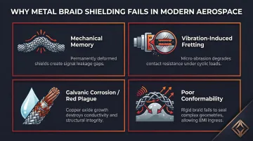
These mechanical failures often surface during qualification testing or in-service operation, when replacement costs dwarf initial material savings.
Depositing a few microns of conductive material onto plastic or composite substrates delivers equivalent or superior shielding to bulk metal. Shielding performance depends on electrical conductivity, not physical mass — which is precisely what thin-film coating processes are engineered to provide.
Types of Lightweight EMI Coatings for Aerospace Applications
"Lightweight EMI coating" encompasses distinct technologies suited to different substrates, geometries, production scales, and performance targets. Selecting the right approach requires understanding what each method deposits, typical thicknesses, and resulting shielding effectiveness.
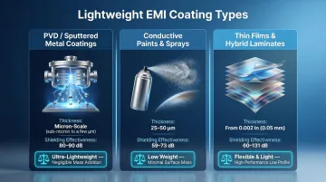
PVD and Sputtered Metal Coatings
Physical vapor deposition (PVD) and magnetron sputtering deposit extremely thin conductive metal films (nickel, silver, copper, titanium nitride, or zirconium nitride) atom-by-atom onto substrates. These processes achieve uniform, well-adhered coatings measured in microns rather than millimeters.
Performance data reflects the method's precision: direct current magnetron sputtering of 4 μm-thick NiFe/Cu layers achieves 80–90 dB shielding effectiveness across 0.7 to 10 GHz. Similarly, electron beam evaporation of 5 μm aluminum layers on plastics yields 80 dB magnetic attenuation at gigahertz frequencies.
Key advantages for aerospace:
- Mass addition is negligible compared to shielding performance—micron-scale coatings add less than 1% to substrate weight
- Ideal for plastic and composite housings, connector bodies, UAV enclosures
- Enables manufacturers to retain weight savings of engineering plastics while gaining metallized conductive surfaces
- Applicable to complex geometries and precision parts
Providence Metallizing Company brings decades of experience applying sputtered metals specifically for EMI-RFI applications across engineering-grade plastics including Ultem and LCP. Their magnetron sputtering and PVD processes can deposit conductive layers on substrates where traditional plating fails to adhere.
Conductive Paints and Spray Coatings
Conductive paints incorporate metallic fillers (nickel, silver, or copper) suspended in acrylic or epoxy vehicles. They can be sprayed, brushed, or dip-applied to enclosures, shielded compartments, and structural panels—making them field-applicable and scalable.
Surface resistivity ranges by filler type:
- Silver-filled acrylics: 0.01–0.03 Ω/sq at 25 μm thickness, delivering ~70 dB SE
- Silver acrylic alternatives: <0.01 Ω/sq at 50 μm, achieving 73 dB ± 11 dB SE
- Nickel acrylics: 0.49 Ω/sq at 50 μm, providing 59 dB ± 12 dB SE
Lower surface resistivity correlates directly with better low-frequency shielding effectiveness. That said, conductive paints vary in adhesion durability, temperature resistance, and long-term performance under thermal cycling or chemical exposure compared to PVD or plated coatings.
Substrate preparation and coating selection become critical to aerospace qualification. Improper surface treatment leads to coating delamination during environmental testing.
Thin Conductive Films and Hybrid Laminates
Conductive films consist of metal-coated polymer substrates (PET, FEP) available in thicknesses as low as 0.002 inches. These die-cuttable, conformable films are suitable for wrapping cable bundles, lining enclosure panels, or sealing apertures. A 2-mil aluminum film provides 60 dB SE at 30 MHz, declining to 45 dB at 1500 MHz—delivering approximately half the weight of equivalent aluminum sheet.
Hybrid laminates combine conductive film or mesh layers with adhesive or structural backing, allowing engineers to integrate EMI shielding directly into composite layups or bond it to existing airframe panels. Combining stainless steel and copper wire mesh with carbon fiber reinforced polymer achieves an EMI SE of 131.6 dB—using the structural component's mass rather than adding separate shielding hardware.
Performance Benchmarks: What Lightweight EMI Coatings Must Actually Deliver
Shielding Effectiveness Thresholds by Application
Military-grade avionics and communication systems typically require shielding effectiveness exceeding 100 dB. Standard signal line shielding targets 60–80 dB. Space systems need additional radiation shielding considerations. Compliance with standard electromagnetic shielding rules typically requires 30 to 40 dB of SE as a baseline.
Achieving these figures with lightweight coatings requires both appropriate material selection and complete coverage without gaps or apertures. A single poorly shielded connector or unsealed seam can compromise an otherwise well-protected assembly — which is why surface resistivity matters as much as material choice.
Surface Resistivity and Transfer Impedance
Surface resistivity (Ω/square) determines how effectively the coating conducts and distributes induced currents. Lower surface resistivity means lower transfer impedance and better low-frequency shielding. A thin sheet with surface resistivity of 0.1 Ω/sq provides over 50 dB of shielding at frequencies above 1 MHz. Materials with surface resistivity less than 0.001 Ω/sq approach solid metal shielding performance.
Target values for aerospace-grade coatings:
- PVD/sputtered coatings: Typically achieve <0.01 Ω/sq
- Silver-filled paints: 0.01–0.03 Ω/sq
- Nickel-based paints: 0.1–1.0 Ω/sq
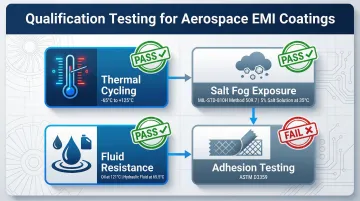
Environmental Durability as Pass/Fail Criteria
A lightweight coating that achieves excellent initial shielding but degrades under environmental exposure fails qualification — regardless of how well it performed at initial test. Qualification testing typically covers four areas:
- Thermal cycling (-65°C to +125°C): Resistance measurements taken before and after to verify coating integrity across the aerospace operating range
- Salt fog exposure: MIL-STD-810H Method 509.7 requires a 5±1% salt solution maintained at 35±2°C
- Fluid resistance: MIL-PRF-23377 requires 24-hour immersion in lubricating oil at 121±3°C and hydraulic fluid at 65.5±3°C
- Adhesion: Cross-hatch or tape tests per ASTM D3359, conducted before and after environmental cycling
Outgassing Requirements for Space Applications
ASTM E-595 testing is especially consequential in vacuum environments: volatile components that off-gas from coatings can condense on optical sensors, solar cells, or antenna apertures, causing permanent performance loss. NASA's acceptance threshold requires Total Mass Loss (TML) below 1.0% and Collected Volatile Condensable Materials (CVCM) at or below 0.1%.
Material selection at this stage is straightforward:
- Pass: Well-cured PVD films and low-VOC conductive adhesives typically meet both thresholds
- Fail: Many solvent-based conductive paints cannot meet CVCM limits and are disqualified from space-qualified assemblies
Aerospace Standards and Compliance for EMI Coatings
Primary Military and Commercial Standards
Three standards govern most aerospace EMI coating qualification work in the US:
| Standard | Published | Scope |
|---|---|---|
| MIL-STD-461G | December 2015 | EMI emission and susceptibility limits for military equipment — aircraft, spacecraft, and ground systems |
| RTCA DO-160G | 2010 (DO-160H planned March 2026) | Airborne equipment environmental and EMI test conditions; Section 22 covers lightning-induced transient susceptibility (referenced by FAA AC 21-16G) |
| MIL-STD-810H | January 2019 | Environmental durability testing — thermal cycling, vibration, humidity, and salt fog exposures |
What Compliance Means Practically
Compliance is validated through system-level testing of the complete shielded assembly — not certification of the coating material in isolation. The coating must maintain its conductive properties after every environmental exposure specified for the platform's qualification test sequence.
AS9100 and ITAR-regulated programs typically require:
- Full documentation of material traceability from raw inputs to finished assembly
- Process control records demonstrating repeatability across production lots
- Retained test data for each qualification exposure (thermal, vibration, humidity, salt fog)
- Conformance review before any material or process substitution
Galvanic Compatibility Requirement
Dissimilar metal combinations between coating and substrate can drive corrosion in humid or salt-spray environments. Nickel and aluminum, for example, form a strong galvanic cell; corrosive exposure produces rapid de-bonding. The same principle applies to CFRP — all contacts between graphite-based composites and metal materials must be treated as dissimilar metal couples and sealed accordingly.
Coating selection requires cross-referencing galvanic series data against the specific substrate: aluminum, titanium, or composite with conductive mesh each carry different compatibility constraints.
Where Lightweight EMI Coatings Deliver the Greatest Value
Military Fixed-Wing and Rotary Aircraft
Avionics bays, cockpit electronics enclosures, and wire harness routing through composite fuselage sections demand shielding that doesn't compromise weight budgets. Thin PVD coatings on plastic enclosures and connector bodies allow designers to meet modern EMI requirements within original design envelopes.
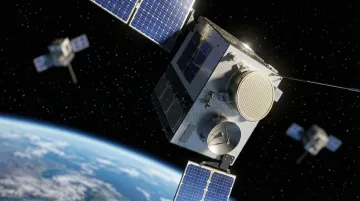
Satellites and LEO Spacecraft
Launch costs to Low Earth Orbit have dropped to approximately $2,720 per kilogram via SpaceX Falcon 9, yet every gram still carries financial and performance consequences. Lightweight coatings make economic sense where traditional shielding would consume launch capacity.
Two technologies illustrate the range of options available. Honeywell's MetShield™ applies 2–5 micron conductive layers on composite substrates, cutting weight by up to 40% versus metal foils while maintaining 60–80 dB SE across 1–18 GHz. ARACON Kevlar-based metal-clad fibers match copper shielding's electrical performance at up to 80% less weight.
UAVs and Unmanned Aerial Systems
Extreme weight sensitivity combined with densely packed electronics makes every shielding gram count. In distributed electric propulsion UAVs, cable mass accounts for 7% of takeoff mass—reducing shielding weight by even 50% delivers measurable improvements in endurance and payload capacity.
Retrofit and Upgrade Scenarios
Legacy military platforms undergoing avionics modernization face a hard constraint: the airframe won't change, but the electronics must. Bays designed decades ago have fixed dimensions and strict weight ceilings that rule out conventional shielding hardware. Thin conductive coatings and sputtered metal treatments address this directly:
- Applied to replacement enclosures and connector bodies without altering form factor
- Add negligible weight compared to sheet metal or foil alternatives
- Meet current EMI standards within the envelope the original designers specified
Across all four scenarios, the common thread is the same: shielding decisions made late create expensive constraints. OEMs and integrators working with experienced metallizing and coating specialists early in the design phase can select and validate the right coating process for their substrate, geometry, and performance requirements before those decisions become locked in.
Frequently Asked Questions
What is the most lightweight EMI coating method for aerospace applications?
PVD/sputtered metal coatings typically deliver the best mass-to-performance ratio by depositing conductive metal layers just microns thick directly onto substrates, with minimal weight addition and no bulk hardware. The optimal method depends on substrate type, production volume, and required shielding effectiveness.
How does PVD sputtered coating compare to conductive paint for EMI shielding?
PVD delivers more uniform coverage, better adhesion, lower surface resistivity, and superior durability—making it the stronger choice for precision parts and complex geometries. Conductive paints are easier to field-apply and scale to large surfaces, but carry higher surface resistivity and lower durability under thermal cycling.
What shielding effectiveness can lightweight EMI coatings achieve?
Lightweight coatings such as PVD, silver-filled paints, and conductive films achieve 60–100+ dB of shielding effectiveness depending on material, thickness, and coverage continuity. This range is sufficient for most avionics, communication, and radar applications when properly applied and grounded.
Can lightweight EMI coatings be applied to composite and plastic aerospace structures?
Yes. PVD/sputtered coatings and conductive paints can be applied to carbon fiber composites, fiberglass, and engineering-grade plastics to impart conductivity and EMI shielding where the base structure has none, without the weight penalty of a metal liner.
What military and aerospace standards govern lightweight EMI coatings?
The primary standards are MIL-STD-461G (emission/susceptibility limits), RTCA DO-160 (airborne equipment EMC and environmental testing), and MIL-STD-810 (environmental durability). Compliance is validated through system-level testing of the coated assembly, not certification of the coating material alone.
How do I verify that a lightweight EMI coating will hold up in harsh aerospace conditions?
Core validation tests include thermal cycling (-65°C to +125°C), salt fog exposure per MIL-STD-810 Method 509, and adhesion and surface resistivity measurements taken before and after each environmental exposure. A qualified coating partner should supply test data covering all three.