Introduction
Imagine a patient-monitoring device flickering just as a nurse transmits data wirelessly, an autonomous vehicle's LiDAR sensor misfiring near high-voltage lines, or audio equipment picking up radio chatter mid-recording. These aren't rare glitches—they're real-world failures caused by radio frequency interference (RFI).
As electronics become denser and wireless signals multiply, RFI has evolved from a minor annoyance into a critical design challenge that can mean the difference between safe operation and catastrophic failure.
This guide covers RFI shielding from the ground up: what it is, how it works, which materials perform best, shielding approaches from component to room level, and how to select the right solution for your application.
TLDR: Key Takeaways
- RFI is electromagnetic disturbance in the radio spectrum (3 kHz–300 GHz)—a subset of EMI
- Shielding works through three mechanisms: reflection, absorption, and grounding
- Copper, aluminum, silver, and nickel are the primary conductive shielding materials
- Protection scales from package and board level up to full shielded rooms
- Aerospace, medical, and automotive industries rely on RFI shielding for safety and compliance
What Is RFI Shielding? Understanding the Basics
Radio Frequency Interference (RFI) refers to electromagnetic disturbance occurring within the radio frequency spectrum, which the FCC and ITU define as 3 kHz to 300 GHz. RFI is a specific subset of Electromagnetic Interference (EMI)—all RFI is EMI, but not all EMI is RFI. In practice, this means RFI-specific shielding solutions target a defined frequency range, while broader EMI protection may need to account for lower-frequency disturbances as well.
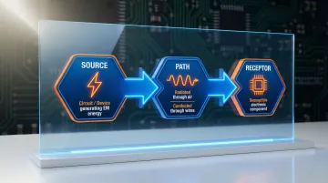
The Three-Component RFI Model
Every RFI disruption involves three elements:
- Source — A circuit or device generating electromagnetic energy
- Path — The route interference travels (conducted through wires or radiated through air)
- Receptor — A susceptible electronic component affected by the interference
Understanding whether your interference is radiated (traveling through air) or conducted (traveling through power lines and cables) determines which shielding approach will actually work.
What Is RFI Shielding?
RFI shielding is a barrier made from conductive or magnetic materials placed between an interference source and sensitive electronics to attenuate (reduce) the interfering signal's strength. Shielding Effectiveness (SE) is measured in decibels (dB) on an exponential scale:
- 10 dB = 10× reduction in signal strength
- 20 dB = 100× reduction
- 30 dB = 1,000× reduction
Highly effective shields typically achieve 90–120 dB of attenuation — the range required by aerospace, medical, and military-grade electronics applications.
How Does RFI Shielding Work?
RFI shielding relies on three core mechanisms to protect sensitive electronics:
- Reflection — repels electric fields at the material surface
- Absorption — converts electromagnetic energy into heat within the material
- Redirection and grounding — routes interference safely away from sensitive components
Each mechanism targets different frequency ranges and interference types. Most real-world shielding solutions combine all three.
Reflection: The Primary Defense Against Electric Fields
When an electromagnetic wave hits a conductive surface, free electrons generate a counteracting field that reflects the wave back toward its source. This works because of the large impedance mismatch between the incoming wave and the material.
Highly conductive metals — copper, silver, and aluminum — excel at reflection for this reason. For high-impedance electric fields and plane waves, reflection provides the bulk of shielding effectiveness.
Absorption: Converting Energy to Heat
As electromagnetic energy penetrates shielding material, oscillating free electrons convert it into heat. Magnetic materials like ferrites are particularly effective absorbers for high-frequency signals.
The skin effect matters here: at higher frequencies, current concentrates near the conductor's surface, reducing absorption depth while exponentially increasing shielding effectiveness.
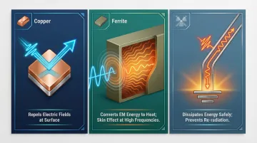
Redirection and Grounding: Completing the Circuit
In cable shielding and enclosure designs, interference is intentionally routed to a ground point where it dissipates safely. Proper grounding is critical — a floating (ungrounded) shield can actually re-radiate interference, making interference worse.
The Faraday Cage: Creating a Neutral Interior Zone
A continuous conductive enclosure surrounds sensitive components and redistributes electromagnetic fields around its exterior, creating a neutral interior zone. A common misconception is that small holes are acceptable as long as their diameter is smaller than the wavelength being blocked. Seams and gaps are the real vulnerability: EM waves slip through even tiny continuous openings between improperly bonded surfaces.
Rule of thumb: To maintain at least 20 dB of shielding, apertures should be no larger than λ/20 (1/20 of the wavelength at the highest frequency of concern).
Testing and Validation Standards
Engineers should know these key standards:
| Standard | Scope | Status |
|---|---|---|
| ASTM D4935 | Planar materials (30 MHz–1.5 GHz) | Active (2018) |
| MIL-STD-461 | Military/defense EMC requirements | Active (Rev G, 2015) |
| IEEE 299-2006 | Enclosure effectiveness (9 kHz–18 GHz) | Active |
| IEC 60601-1-2 | Medical device EMC | Active (Edition 4.1) |
| MIL-STD-285 | Enclosure attenuation (legacy) | Canceled 1997 — superseded by IEEE 299 |
Best Materials for RFI/EMI Shielding
Conductive Metals
The most common shielding metals each serve specific needs:
- Copper — Excellent conductivity, best for electric field/high-impedance wave reflection
- Aluminum — Lightweight, good conductivity, common in enclosures
- Silver — Highest conductivity but expensive, used in high-performance paints and gaskets
- Nickel — Corrosion-resistant, used in coatings and gaskets
- Steel/Stainless Steel — Good for magnetic field absorption, lower conductivity
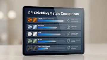
The choice depends on whether the dominant interference is electric-field (high-impedance) or magnetic-field (low-impedance).
Shielding Gaskets
Conductive gaskets use metal fillers (silver, silver-aluminum, silver-nickel, nickel-graphite) suspended in flexible bases (typically silicone or fluorosilicone) to seal enclosure joints and prevent EM leakage through seams. Temperature extremes affect gasket performance, and material selection must account for operating environment.
Critical consideration: Mating silver-filled elastomers with aluminum enclosures causes severe galvanic corrosion. Nickel-aluminum or silver-aluminum fillers significantly reduce flange pitting.
Conductive Coatings and Vacuum Metallizing
Conductive paints and coatings offer a cost-effective alternative to solid metal enclosures for plastic housings. When EM waves contact conductive coatings, they undergo the same reflection and absorption as bulk metal—performance depends on coating thickness and conductivity.
Coating options:
- Silver-based paints — Highest shielding performance (up to 89 dB at 1 mil thickness)
- Nickel-based paints — Balance of cost and effectiveness (~60 dB at 1 mil)
- Water-based variants — Suited to architectural (room-level) applications
Vacuum metallizing (PVD/magnetron sputtering) deposits ultra-thin conductive metal films directly onto plastic substrates, providing effective RFI shielding without adding significant weight. Vacuum-deposited aluminum provides 60–80 dB attenuation, while copper achieves 70–90 dB.
Providence Metallizing Company introduced magnetron sputtering for EMI-RFI applications in the 1980s. This process applies conductive layers to complex plastic enclosures with consistent coverage and adhesion — useful for electronics housings where bulk metal construction isn't practical.
Magnetic and Composite Materials
Ferrites and magnetic alloys absorb high-frequency magnetic interference rather than reflecting it, making them the right choice for transformer shielding, cable cores, and applications where reflected energy would cause secondary interference. NiZn ferrites work up to 300 MHz, while MnZn ferrites handle lower frequencies below 50 MHz.
When a single material type can't cover the full frequency range, composite shields combining conductive and magnetic layers fill the gap. Combining MnZn ferrite with mu-metal film, for instance, increased shielding by 22.3× compared to ferrite alone.
Types of RFI Shielding: From Components to Rooms
Package-Level Shielding
Package-level shielding targets individual components or ICs to prevent their emissions from disrupting neighboring components. Metal cans remain common, but conductive paints applied at just 8 µm directly onto packaged components are now widely used. These ultra-thin coatings achieve >90 dB of shielding across MHz to GHz frequencies, with meaningful reductions in weight, cost, and board footprint.
Board-Level Shielding
Scaling up from individual components, board-level shielding (BLS) uses metal enclosures — typically a frame soldered to the PCB with a removable lid — to surround specific high-emission or high-susceptibility circuits.
Design considerations:
- Aperture size: Keep holes ≤ λ/20 of the target wavelength to prevent leakage
- Flatness: Uneven frames compromise the solder joint and undermine shielding continuity
- Cavity resonance: Enclosure dimensions can create resonant frequencies that amplify interference — add RF absorbers internally to mitigate
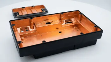
Device-Level Shielding
Where board-level shielding handles individual circuits, device-level shielding protects entire product housings — typically by lining plastic enclosures with conductive coatings or using metal housings. This matters for EV battery packs, medical instruments, and industrial controllers. Internal circuits need protection from external interference, and the device itself must not contaminate surrounding electronics with its own emissions.
Room-Level Shielding
Room-level or architectural shielding (Faraday rooms) is used in server rooms, surgical suites, MRI rooms, and sensitive testing environments. Methods include conductive mesh embedded in walls, conductive architectural paints, and specialized door/window seals. MRI suites require 80–100 dB of attenuation (10–130 MHz) to prevent external RF from causing image artifacts. Water-based conductive paints are practical for drywall applications and can be painted over with standard finishes.
Where Is RFI/EMI Shielding Used? Key Industries
Aerospace and Defense
Avionics, radar, communications equipment, and weapons systems must pass MIL-STD-461 requirements—failure represents a safety risk. Shielding isn't optional; it's mission-critical.
Medical Devices
Patient monitoring, imaging, and implantable devices must meet IEC 60601-1-2 to avoid life-threatening malfunctions from interference. When a pacemaker or ventilator malfunctions due to RFI, lives are at stake.
Automotive and Electric Vehicles
Modern vehicles contain 60–100+ ECUs (Electronic Control Units), and EVs push this to 80–100 units—nearly double traditional combustion vehicles. EVs add high-voltage drivetrains that are both significant EMI sources and vulnerable to it. Autonomous vehicles depend on LiDAR and radar sensors that must be shielded to function reliably.
Telecommunications
5G infrastructure introduces millimeter-wave spectrum (24–52.6 GHz) and denser small-cell base station deployments. Higher frequencies and massive MIMO beamforming increase EMI complexity, requiring more rigorous shielding in base stations and end devices.
Additional Sectors
RFI shielding requirements extend across many other sectors as well:
- Industrial equipment — motors, power converters, and PLCs generate and absorb interference in factory environments
- Consumer electronics — smartphones and laptops require shielding to meet FCC Part 15 emissions limits
- Scientific environments — RF-shielded test chambers and MRI labs depend on near-total signal isolation
- IoT devices — with deployments potentially reaching 200,000 devices per km², even everyday connected objects need shielding
This broad demand is reflected in the numbers: the global EMI shielding market was valued at $6.99 billion in 2023 and is projected to reach $9.69 billion by 2029, growing at a 5.7% CAGR.
How to Choose the Right RFI Shielding Solution
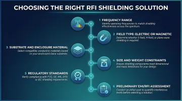
Selecting the right shielding approach requires evaluating several key factors:
- Frequency range of the interference — determines material type and aperture size
- Field type — electric or magnetic (determines whether reflection or absorption is priority)
- Substrate/enclosure material — metal vs. plastic, rigid vs. flexible
- Size and weight constraints
- Regulatory standards for your target industry
- Preliminary EMI/RFI assessment — complete this before specifying any solution
Design-Phase vs. Retrofit: Why Early Integration Costs Less
Integrating shielding early in the design process is far more cost-effective than retrofitting after production. The trade-offs:
| Approach | SE | Weight | Cost | Best For |
|---|---|---|---|---|
| Metal enclosures | 90–120+ dB | Heavy | High | Maximum protection |
| Conductive coatings/PVD | 60–90 dB | Very light | Medium | Plastic substrates, complex geometries |
| Gaskets | Up to 120 dB at seams | Light | Varies | Sealing enclosure joints |
Work with experienced metallizing or shielding partners who can advise on material performance and manufacturability. Providence Metallizing Company, for example, provides vacuum metallizing and PVD coating services on engineering-grade plastics — including ABS, PC, Ultem, Nylon, and LCP — applying conductive films for EMI-RFI shielding with minimal weight addition.
Frequently Asked Questions
How do you shield RFI?
Surround sensitive electronics with conductive materials — metal enclosures, coatings, gaskets, or metallized plastics — that reflect or absorb interfering signals. All seams must be properly bonded and the shield grounded to prevent re-radiation.
Does RFI shielding need to be grounded?
Grounding is strongly recommended because it provides a low-impedance path for stray electromagnetic energy to dissipate safely. Without grounding, the shield can accumulate charge and re-radiate interference, potentially worsening the problem.
Why is RFI/EMI shielding important?
Shielding prevents interference-induced malfunctions, data corruption, signal degradation, and complete device failure. Consequences range from audio static in consumer electronics to safety-critical failures in medical devices or aircraft systems.
Where is RFI/EMI shielding used?
Shielding is used across aerospace, defense, medical, automotive, telecommunications, and industrial sectors. Any application where devices must operate reliably amid electromagnetic noise — or must contain their own emissions to meet regulatory standards — requires some form of shielding.
What are the best materials for RFI/EMI shielding?
Copper, silver, aluminum, nickel, and steel are the most common conductive shielding metals. The best choice depends on the threat type (electric- or magnetic-field dominant), required attenuation level, and practical constraints like weight and substrate compatibility.
Do EMF-blocking paint or EMI coatings actually work?
Yes, conductive coatings (including silver- and nickel-based paints and vacuum-deposited metal films) provide measurable shielding effectiveness when properly applied. Performance depends on the coating's conductivity, thickness, and how well seams and edges are bonded.